Thank you for choosing Toan Phat's three-phase squirrel-cage induction motor.
Please read this manual carefully before operation and review the technical specifications on the motor label.
I. Motor Installation
- Surrounding Environment
-
Ensure the motor is installed in a cool, dry place, free from steam and chemicals that could reduce its durability (except for specially designed motors with specific codes).
-
Ensure the motor’s ventilation path is unobstructed.
- Assembly
a. Coupling Assembly
-
The coupling is mounted on the shaft by heating or directly pressing onto the shaft end. When pressing the coupling onto the shaft, ensure protection for the rear end of the shaft to avoid damaging the bearings and other components.
-
Ensure the alignment of the two shafts.
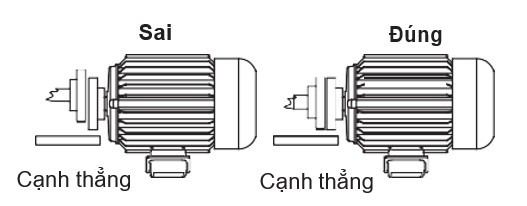
- The angle between the motor side coupling and the load side coupling should be zero.
- The system should rotate the coupling smoothly after assembly; improper assembly can lead to shaft breakage.
b. Pulley and Belt Assembly
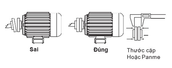
-
The pulley is mounted on the shaft by heating or directly pressing onto the shaft end. When pressing the pulley onto the shaft, ensure protection for the rear end of the shaft to avoid damaging the bearings and other components.
-
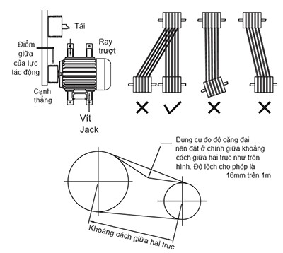
Ensure the parallel alignment of the motor shaft and the driven machine shaft during installation. The belt should not be too tight to avoid excessive force on the shaft, negatively affecting the bearing.
-
Proper assembly ensures an even distribution of belt tension across the pulley and shaft.
-
The pulley should always be flush against the shaft shoulder and tightly secured on the shaft.
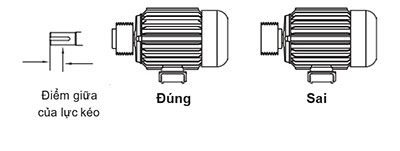
-
Typically, the main load point on the pulley should be at the midpoint of the shaft end.
II. Pre-Operation Inspection.
- After installing the three-phase electric motor, the following checks should be conducted before operation:
- Mechanical Inspection
-
Ensure all connections are secure and meet technical requirements.
-
Ensure the motor shaft can rotate freely before initial startup.
-
Rotate the motor shaft at least one full turn to ensure no contact between rotating and stationary parts.
-
Tighten all bolts and nuts on the motor and the working machine; secure the four base or flange bolts to the support or equipment.
-
Ensure no loose parts can be sucked into the motor's cooling fan.
- Electrical Inspection
-
Ensure all electrical connections are secure and continuous.
-
Check the operation of overload protection devices, all switches, fuses, and motor protection devices to ensure proper startup characteristics.
-
Verify that the supply voltage and frequency match the motor’s specifications on the label.
-
Check the connection diagram in the motor’s terminal box and ensure all main motor connections are secure and not short-circuited or grounded.
-
Ground the motor housing via the ground bolt attached to the motor body.
-
Open the motor’s terminal box, separate the three stator phases, and use a 1000V Megger to check the insulation resistance between phases and between phase and housing. Insulation resistance values should be:
-
- Phase-Phase Rcđ ≥ 5MW
- Phase-Housing Rcđ ≥ 10MW
- If the insulation resistance is below these values, dry the stator windings until the required values are achieved before connecting to the power supply for operation.
- The wires connected to the motor must meet the insulation and cross-sectional area requirements specified in the table:
| No. | Motor Power | Cable Cross-Section per Phase (mm²) | Notes |
| 1 | 0.55kW/1.1 kW – 6P/4P- 380V/380V | ≥0.75 / ≥0.75 | 06 leads |
| 2 | 0.75kW/1.1 kW – 6P/4P- 380V/380V | ≥0.75 / ≥0.75 | 06 leads |
| 3 | 0.75kW/1.5 kW – 6P/4P- 380V/380V | ≥0.75 / ≥1.0 | 06 leads |
| 4 | 1.1kW/2.2 kW – 6P/4P- 380V/380V | ≥0.75 / ≥1.5 | 06 leads |
| 5 | 2.2kW/2.4 kW – 6P/4P- 380V/380V | ≥1.5 / ≥1.5 | 06 leads |
| 6 | 1.5kW/2.2kW – 6P/4P- 380V/380V | ≥1.0 / ≥1.5 | 06 leads |
| 7 | 1.1kW/3.0kW – 6P/4P- 380V/380V | ≥0.75 / ≥1.5 | 06 leads |
| 8 | 1.5kW/3.0kW – 6P/4P- 380V/380V | ≥1.0 / ≥1.5 | 06 leads |
| 9 | 1.5kW/4.0kW – 4P/2P- 380V/380V | ≥1.0 / ≥3.0 | 06 leads |
| 10 | 1.5kW/4.0kW – 6P/4P- 380V/380V | ≥1.0 / ≥3.0 | 06 leads |
| 11 | 2.2kW/3.0kW – 6P/4P- 380V/380V | ≥1.5 / ≥1.5 | 06 leads |
| 12 | 2.2kW/4.0kW – 4P/2P- 380V/380V | ≥1.5 / ≥3.0 | 06 leads |
| 13 | 2.2kW/4.0kW – 6P/4P- 380V/380V | ≥1.5 / ≥3.0 | 06 leads |
| 14 | 2.2kW/5.5kW – 6P/4P- 380V/380V | ≥1.5 / ≥3.0 | 06 leads |
| 15 | 3.0kW/5.5kW – 6P/4P- 380V/380V | ≥1.5 / ≥3.0 | 06 leads |
| 16 | 3.0kW/7.5kW – 6P/4P- 380V/380V | ≥1.5 / ≥4.0 | 06 leads |
| 17 | 4.0kW/11kW – 6P/4P- 380V/660V | ≥3.0 / ≥8.0 | 12 leads |
| 18 | 4.0kW/15kW – 6P/4P- 380V/660V | ≥3.0 / ≥8.0 | 12 leads |
| 19 | 4.0kW/7.5kW – 6P/4P- 380V/660V | ≥3.0 / ≥4.0 | 06 leads |
| 20 | 5.5kW/7.5kW – 6P/4P- 380V/380V | ≥3.0 / ≥4.0 | 06 leads |
| 21 | 5.5kW/11kW – 6P/4P- 380V/660V | ≥3.0 / ≥8.0 | 12 leads |
| 22 | 5.5kW/15kW – 6P/4P- 380V/660V | ≥3.0 / ≥8.0 | 12 leads |
| 23 | 5.5kW/18.5kW – 6P/4P- 380V/660V | ≥3.0 / ≥16 | 12 leads |
| 24 | 7.5kW/11kW – 6P/4P- 380V/660V | ≥4.0 / ≥8.0 | 12 leads |
| 25 | 3.0kW/7.5kW – 6P/4P- 380V/380V | ≥1.5 / ≥4.0 | 06 leads |
| 26 | 4.0kW/7.5kW – 6P/4P- 380V/380V | ≥3.0 / ≥4.0 | 06 leads |
| 27 | 7.5kW/15kW – 6P/4P- 380V/660V | ≥4.0 / ≥8.0 | 12 leads |
| 28 | 7.5kW/18.5kW – 6P/4P- 380V/660V | ≥4.0 / ≥16 | 12 leads |
| 29 | 11kW/18.5kW – 6P/4P- 380V/660V | ≥8.0 / ≥16 | 12 leads |
| 30 | 11kW/22kW – 6P/4P- 380V/660V | ≥8.0 / ≥16 | 12 leads |
| 31 | 11kW/30kW – 6P/4P- 380V/660V | ≥8.0 / ≥16 | 12 leads |
| 32 | 15kW/30kW – 6P/4P- 380V/660V | ≥8.0 / ≥16 | 12 leads |
| 33 | 18.5kW/22kW – 6P/4P- 380V/660V | ≥16 | 12 leads |
- Wiring Diagram for Terminal Board of Electric Motors with Voltages 380V/380V, 380V/660V:
- For motors with an operating voltage indicated on the label as 380V/380V, 6 leads, type 6P/4P:
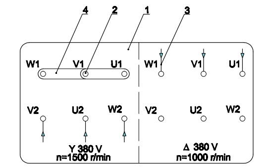
-
Terminal Board
-
Terminal Post
-
Three-Phase Power Supply Wires
-
Bridging Connectors
- For motors with an operating voltage indicated on the label as 380V/660V, 12 leads, type 6P/4P:
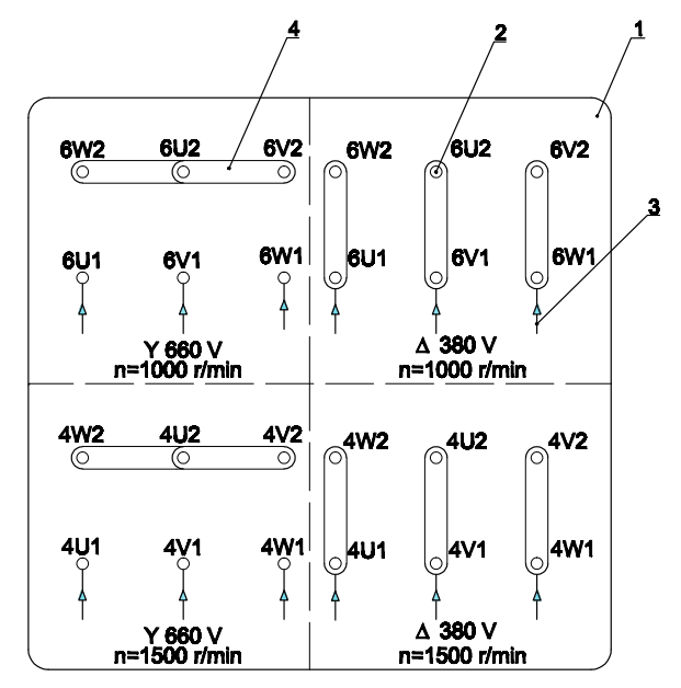
-
Terminal Board
-
Terminal Post
-
Three-Phase Power Supply Wires
-
Bridging Connectors
- For motors with an operating voltage indicated on the label as 380V/380V, 6 leads, type 4P/2P:
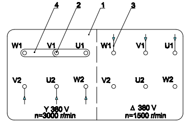
-
Terminal Board
-
Terminal Post
-
Three-Phase Power Supply Wires
-
Bridging Connectors
- For motors with an operating voltage indicated on the label as 380V/660V, 12 leads, type 4P/2P:
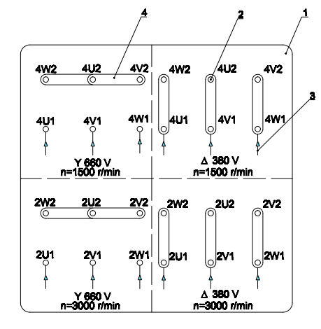
-
Terminal Board
-
Terminal Post
-
Three-Phase Power Supply Wires
-
Bridging Connectors
III. Operation
-
Before running the motor, ensure the terminal box cover is closed, and the area is clear of tools and debris.
-
Make sure the motor housing is grounded.
-
Confirm the load is within the motor’s specifications.
-
Ensure the working environment is dry and cool, and prevent water, oil, and other liquids from entering the motor.
After startup, if the motor runs smoothly without vibrations or strange noises, it is ready for operation. If any issues arise, stop and recheck the mechanical and electrical assembly. Always monitor the motor during operation.
Note: If restarting after a long idle period or in an unprotected environment, check the winding insulation resistance. Disconnect all cables and clean the motor exterior before measuring.
IV. Motor Storage and Maintenance
- Storage
After a period of operation or prolonged inactivity, follow these steps:
-
Keep the motor exterior clean to prevent dirt buildup and rust, preserving its appearance.
-
Store the motor in a dry place to avoid the effects of environmental factors like rain and humidity, which can reduce the insulation of the stator windings.
2. Maintenance
-
Lubricate bearings.
-
After 700 to 1000 hours of operation, add grease through the grease fitting on the motor cover or remove the cover, clean, dry, and grease 2/3 of the bearing.
- Motor Maintenance Schedule
| Task Description | Work Details |
| General Inspection | Review the current operational status and safety system. |
| Inspect Bearings and Drive Belts | Check wear and tear, adjust, repair, or replace as necessary. |
| Check Motor-Related Components | Check motor parameters such as temperature, vibration, and compare with initial values |
| Clean Motor and Operation Area | Clean the motor and surrounding area to ensure efficient operation. |
| Motor Characteristics | Check motor parameters such as temperature, vibration, and compare with initial values. |
| Inspect Bearings | Ensure bearings are lubricated as recommended by the manufacturer. |
| Check Tightness in Terminal Box | Check and tighten all electrical connections. |
| Check Balance of 3-Phase Power | Correct and repair any issues if the voltage imbalance exceeds 1%. |
Comment